81 Results
View results:
Sort by:

The fatigue design according to EN 1992-1-1 must be performed for the structural components subjected to large stress ranges and/or many load changes. In this case, the design checks for the concrete and the reinforcement are performed separately. There are two alternative design methods available.

If you want to use a pure surface model, for example, when determining the internal forces and moments, but the structural component is still designed on the member model, you can take advantage of a result beam.

To be able to evaluate the influence of local stability phenomena of slender structural components, RFEM 6 and RSTAB 9 provide you with the option of performing a linear critical load analysis on the cross-section level. The following article explains the basics of the calculation and the result interpretation.

With the Steel Design add-on, you can design structural steel components in the event of fire using the simple design methods according to Eurocode 3. The component temperature at the time of the design check can be determined automatically according to the temperature-time curves specified in the standard. In addition to considering a cladding for fire protection, it is also possible for you to take account of the beneficial properties of hot-dip galvanization.

Steel connections in RFEM 6 can be created by simply entering predefined components in the Steel Joints add-on. The collection of these components is constantly being improved to make your work even easier even when modeling steel connections. In this article, the connection plate component is introduced as a component recently added to the add-on's library.

The advantage of the RFEM 6 Steel Joints add-on is that you can analyze steel connections using an FE model for which the modeling runs fully automatically in the background. The input of the steel joint components that control the modeling can be done by defining the components manually, or by using the available templates in the library. The latter method is included in a previous Knowledge Base article titled “Defining Steel Joint Components Using the Library". The definition of parameters for the design of steel joints is the topic of the Knowledge Base article “Designing Steel Joints in RFEM 6".

Steel connections in RFEM 6 are defined as an assembly of components. In the new Steel Joints add-on, universally applicable basic components (plates, welds, auxiliary planes) are available for entering complex connection situations. The methods with which connections can be defined are considered in two previous Knowledge Base articles: “A Novel Approach to Designing Steel Joints in RFEM 6" and “Defining Steel Joint Components Using the Library".

You can use the Steel Joints add-on in RFEM 6 to create and analyze steel connections using an FE model. You can control the modeling of the connections via a simple and familiar input of components. Steel joint components can be defined manually, or by using the available templates in the library. The former method is included in a previous Knowledge Base article titled “A Novel Approach to Designing Steel Joints in RFEM 6". This article will focus on the latter method; that is, it will show you how to define steel joint components using the available templates in the program’s library.

According to EN 1992-1-1 [1], a beam is a member of which the span is no less than 3 times the overall section depth. Otherwise, the structural element should be considered as a deep beam. The behavior of deep beams (that is, beams with a span less than 3 times the section depth) is different from the behavior of normal beams (that is, beams with a span that is 3 times greater than the section depth).
However, designing deep beams is often necessary when analyzing the structural components of reinforced concrete structures, since they are used for window and door lintels, upstand and downstand beams, the connection between split-level slabs, and frame systems.

Imperfections in construction engineering are associated with production-related deviation of structural components from their ideal shape. They are often used in a calculation to determine the equilibrium of forces for structural components on a deformed system.

Steel has poor thermal properties in terms of fire resistance. The thermal expansion for increasing temperature is very high compared to that of other building materials, and might result in effects that were not present in the design at normal temperature due to restraint in the component.As temperature increases, steel ductility increases, whereas its strength decreases. Since steel loses 50% of its strength at temperature of 600 °C, it is important to protect components against fire effects. In the case of protected steel components, the fire resistance duration can be increased due to the improved heating behavior.
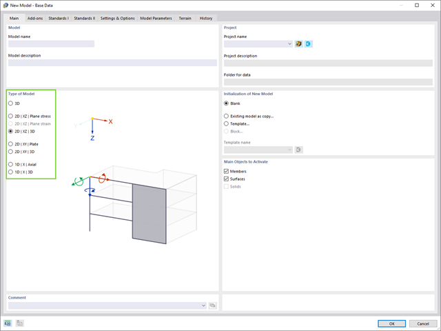
Structures are three-dimensional in reality; however, they can be simplified and analyzed as 2D or 1D models. The model type has a crucial influence on how the structural components are stressed, and it should be defined prior to modeling and calculation.

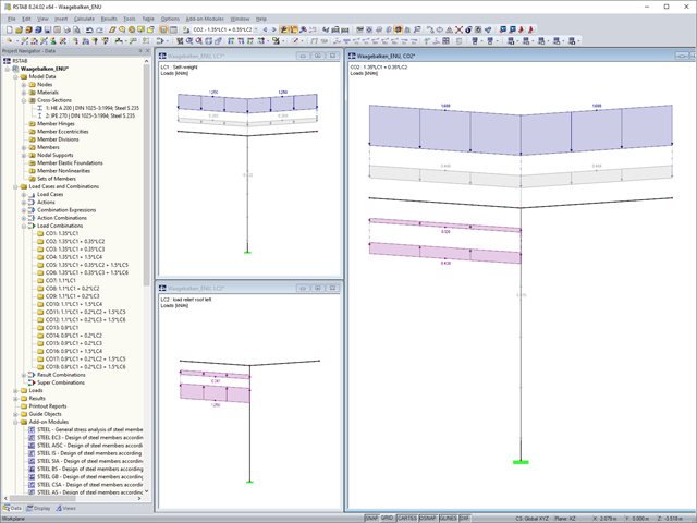
The add-on modules for designing structural member components according to national, European, and international standards also show design results in addition to numerical output in tables graphically, as diagrams displayed on the framework.

An FE mesh quality display is available in RFEM as a tool for structural analyses of two-dimensional components. It leads to the execution of an internal check of the generated finite elements for defined criteria.

The reinforced concrete design for fire situations is carried out according to the simplified method based on EN 1992-1-2, Clause 4.2. The "zone method" described in Annex B.2 is used: The cross-section is subdivided into a number of parallel zones of equal thickness, and their temperature-dependent compressive strength is determined. The reduced load-bearing capacity in the event of fire exposure is thus represented by a reduced structural component's cross-section with reduced strengths.

In the case of using slow‑curing concrete (usually for thick components), you can reduce the calculated minimum reinforcement by a factor of 0.85 to apply the load due to restraint, according to EN 1992‑1‑1, Section 7.3.2. However, a precondition for reduction is that the characteristic value of the strength development r = fcm2 / fcm28 does not exceed 0.3. Other key requirements for the application of this reinforcement reduction are specified explicitly in the final planning documents.
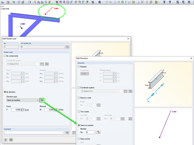
RFEM and RSTAB provide various options for entering nodal loads. These implemented features allow the user to define the nodal loads in relation to different components in space.

For the design of concrete surfaces, the rib component of the internal forces can be neglected for the ULS calculation and for the analytical method of the SLS calculation, because this component is already considered in the member design. To do this, select the check box in the "Details" dialog box. If no rib was defined, this function is not available.
In the case of horizontal beam-like supporting structures, the favorable and unfavorable load components of the permanent actions should be considered separately. In RFEM and RSTAB, you can do this as follows.
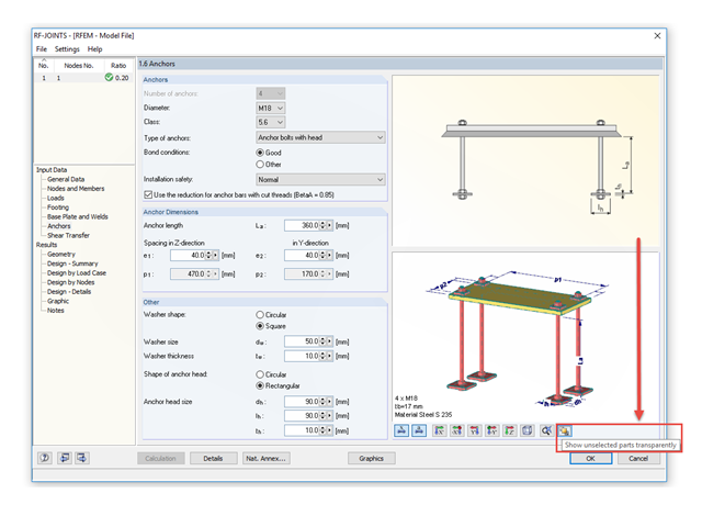
The RF‑/JOINTS add‑on modules are equipped with a graphical window that shows all the structural components of the connection. There, you can use the mouse functions known from RFEM and RSTAB to zoom, move, or rotate the view.
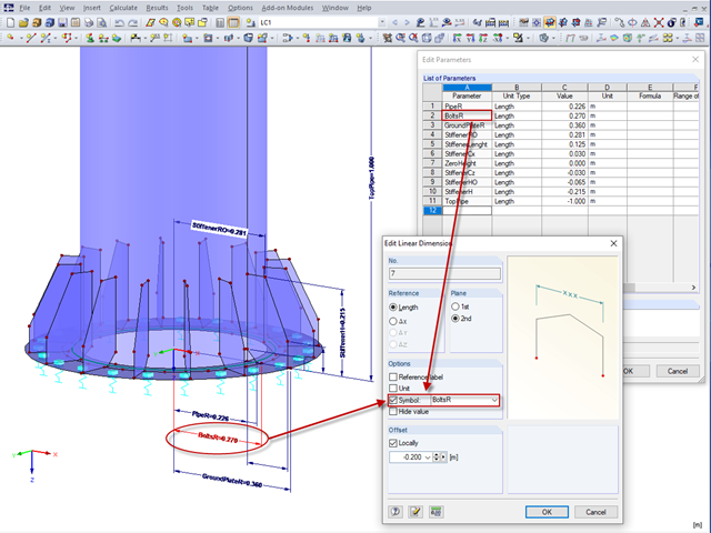
In RFEM 5 and RSTAB 8, it is useful to parameterize frequently occurring components with variable dimensions. In the Block Manager, you then can specify new dimensions and import them in a new or existing file.

In EN 1993-1-1, the General Method was introduced as a design format for stability analyses that can be applied to planar systems with arbitrary boundary conditions and variable structural height. The design checks can be performed for loading in the main load-bearing plane and simultaneous compression. The stability cases of lateral-torsional buckling and flexural buckling are analyzed from the main supporting plane; that is, about the weak component axis. Therefore, the issue often arises as to how to design, in this context, flexural buckling in the main load-bearing plane.

When using the RF‑GLASS add‑on module, you can define just the geometry in the main program, as well as the load situation of the structural component to be designed. The respective support conditions and all further design-relevant definitions (for example, the layer structure and support conditions), can be further specified in RF‑GLASS.
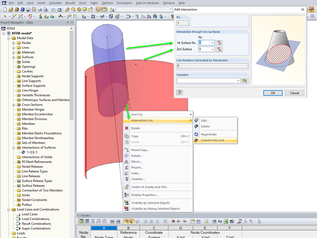
If you want to model two intersecting surfaces, RFEM offers you the possibility to create the section line automatically. In the program, this function is referred to as intersection. When generating an intersection, the modeled surface is split into components. This has the advantage that the components can be taken into account in the determination of the internal forces, or deactivated.
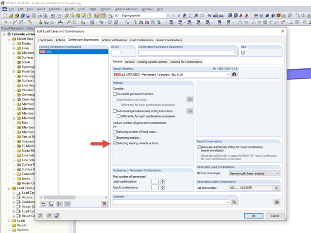
To carry out a structural analysis for a structural system according to the current standards, it is necessary not only to deal with the actions and resistances of structural components, but also with the combinations of these actions. Some of the most common actions in structural analysis are, for example, the permanently acting load case of self‑weight and the suddenly acting load cases of wind and snow.
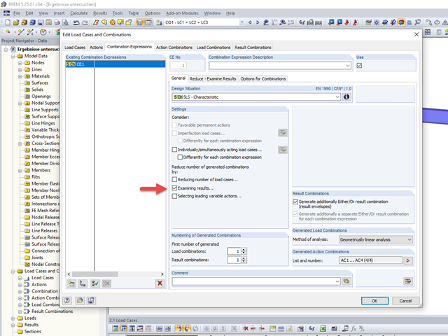
To carry out a structural analysis for a structural system according to the current standards, it is necessary not only to deal with the actions and resistances of structural components, but also with the combinations of these actions. Some of the most common actions in structural analysis are, for example, the permanently acting load case of self‑weight and the suddenly acting load cases of wind and snow.
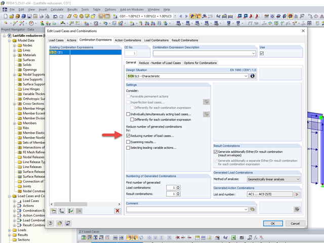
To carry out a structural analysis for a structural system according to the current standards, it is necessary not only to deal with the actions and resistances of structural components, but also with the combinations of these actions. The best-known actions in structural analysis are, for example, the permanently acting load case of self-weight and the suddenly acting load cases of wind and snow.
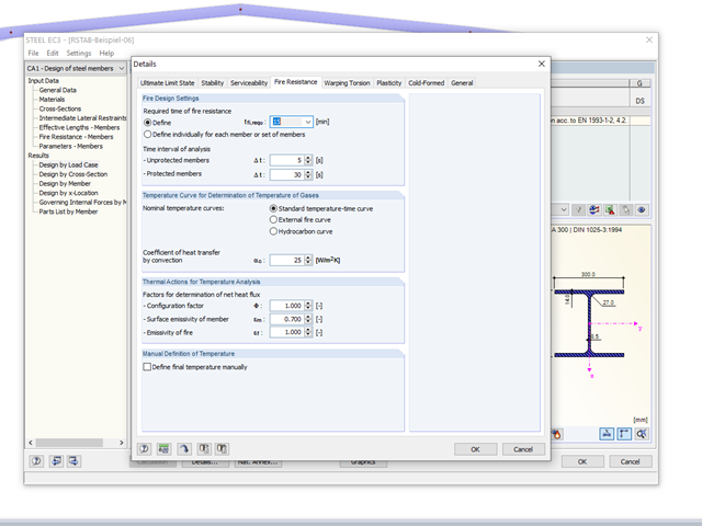
The RF-/STEEL EC3 add‑on module allows for the fire protection design of structural steel components. The simplified analysis is performed by determining the steel temperature iteratively for a particular point of time.
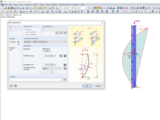
In the world of construction engineering, the word "imperfections" has a specific meaning. In general, it describes the incompleteness of a structure or the deviation of a structural component from an ideal shape caused by the production.
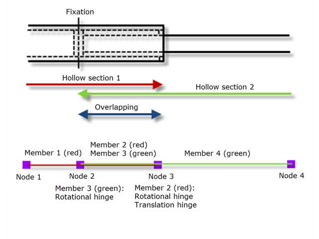
The nested components of a telescopic boom of a construction machine, for example, transport their forces mechanically between the components.